There are different components used in a hydraulic system like valves, which control the flow of liquid in a system. Hydraulic valves are available in different types and sizes depending on the rate of flow and pressure of the system. Basically, they are categorized into directional control, flow control, pressure control, and electro-hydraulic valves. It is important that you choose the valve according to your system requirements, that’s where we can help.
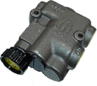
A hydraulic priority flow divider valve is built for applications where two separate hydraulic power circuits are served by a common pump. It comes with an adjustable and non-adjustable flow in controlled flow circuit. A Hydraulic priority flow divider valve is usually made with a cast iron body to provide increased strength.
At Ryan Hydraulic, we can help you find the hydraulic flow divider valves for your application and we carry a significant stock of valves in various sizes and spool configurations. We also carry an array of other hydraulic accessories like sub-plates, seal kits, O-rings, solenoids and much more.
Priority Flow Divider is designed for applications where two separate hydraulic power circuits are to be run from a single pump. First of all the priority flow divider provides priority flow to the primary circuit. In addition, any excess flow is sent to a secondary circuit or back to the tank. Furthermore, an optional hand adjusting knob with 12 positions is available to adjust the flow from 1 to 20 GPM [3.8 to 76 litres/min] at the controlled-flow port. Flow enters the inlet port and passes through a control orifice. The control orifice size is fixed in the non-adjustable unit or can be varied externally in the adjustable unit. Flow through the control orifice causes a pressure drop, which is sensed across the compensator spool. Any tendency to exceed the flow setting increases this pressure drop causing the spool to shift and bypass the excess flow. If the secondary circuit (excess flow) pressure is greater than the controlled-flow pressure, the spool will shift even further and begin to throttle the controlled-flow to maintain the preset value. If the controlled-flow port is blocked, the compensator spool will return to the closed position allowing no flow through the Flow Divider. To protect the system, if this condition occurs, an optional differential relief valve may be installed in the controlled-flow circuit to ensure flow to the secondary circuit under all operating conditions is maintained.
Features
- Differential Poppet Relief Valve in the controlled-flow circuit – also available without a relief valve.
- Available with an adjustable or non-adjustable flow in a controlled-flow circuit
- Adjustable divider offers 12 flow adjustment positions (positive detents) in 360° rotation of the knob.
- High-Strength Cast Iron Body
- Hardened metering spool.
- Excess flow can be used in a secondary circuit.
Specifications
- Capacity (nominal)….30 GPM [113 litres/min]
- Max operating pressure….3500 PSI [242 bar]
- Minimum operating pressure drop…..70 PSI [4.8 bar]
- Knob Rotation (full adjustment) ………….360°
- Filtration required (min.) …….33 micrometer